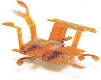
 Flex circuits are a minority sector of the North American PCB fab market — rigid PCBs represent an estimated 90% of the current PCB industry in North America, according to IPC's World PCB Production and Laminate Market Report — but this 10% of the market can be found in every end-use sector from medical to consumer. Mark Finstad and Mark Verbrugge, from Minco, recently spoke to the IPC and SMTA chapters here in New England, providing design and manufacturing best practices for those that are, or would be, using flex circuits in an electronics assembly. Some of their advice may surprise you.
Design best practices are of utmost importance with flex, not least of all because most OEMs and ODMs have only a passing familiarity with the capabilities and limitations of flex circuits. The bend ratio is the fundamental principle of flex design. It describes the ratio of circuit thickness to radius of the circuit bend. Bad bend ratios lead to field failures from rippling and cracked copper. Some other helpful design tips? Design elements that are good for a circuit mechanically are bad for it electrically, so find a balance. Copper thickness and shielding materials can make the difference between a bouncy flex circuit, like that in a flip cell phone, and a flex-to-fit circuit, that will not bend once installed. Finstad and Verbrugge recommend placing small conductors on the inside of the bend; keeping plated thru-holes away from bend areas, and debonding substrates for more flexibility.
Once the flex circuit is fabricated, it must be shipped to the electronics assembler, who will handle and install/form the circuit. Every effort in design and materials specs can be wasted by improper shipping and installation procedures. Forming and handling are the two main causes of flex disasters, according to the Minco engineers. Switching from bags to formed hard plastic packs for shipping will protect circuits from scratches, ESD, and other damage, Finstad and Verbrugge explained, showing us the damage mounted components will do to neighboring flex pads in transit. This method applies to storage and cleaning as well. Have you ever taken a $400 thick, multilayer flex circuit, and bent it over a table edge to form it for assembly? Even if the circuit is $4, this is an undesirable technique. Forming tools, which range from simple to complex, apply uniform and repeatable force and create the specified bend radius every time. ROI is all but guaranteed.
Finstad and Verbrugge have many more tips for successful flex use, and if you’d like to hear them, email mark.finstad@minco.com and mark.verbrugge@minco.com. Since flex circuits are often misunderstood or foreign to electronics assemblers, I’d like to go over a few of the definitions Finstad and Verbrugge presented.
Does a flex circuit really flex? All flex circuits can be exercised, or bent, but the spring in a circuit varies from case to case.
IPC 6013 breaks flex circuits out into four types: single layer (Type 1), double layer (Type 2), multi layer (Type 3), and rigid flex (Type 4).
Type 1 single-layer circuit.

Type 3 multi-layer circuit.

Types 1 and 2 circuits are generally very dynamic, meaning they can be exercised many times without performance-affecting damage. However, layer count isn’t the only determinant for how dynamic a circuit is. Layer thickness differences and materials specs can make two double-layer circuits as different as a Type 1 and Type 3.
Rigid-flex
 Rigid-flex PCBs are a combination circuit, and they are expensive. Some applications, like double-sided surface mount, require the rigid-flex construct; however, the Minco engineers see a lot of unnecessary specs for rigid-flex. If the application calls for single-sided surface mount with flex, mounting a stiffener will do the job. It also will give you a 25–30% cost reduction from rigid-flex.
Stiffener used instead of rigid-flex.
 Materials for the laminates of flex circuits include polyimide/acrylic — which dominates the North American flex market — LCP, and FEP. The copper in a flex circuit can be rolled annealed or electrodeposited, each with pros and cons.
No matter how small flex circuits’ slice of the overall circuit board market is, they can make or break a design. Spending some time familiarizing yourself with the terminology and methodology of flex can lead to better assemblies and smarter budgets, as well as deeper PCB fab relationships. One trade association meeting, or one class at a tradeshow conference, can pay exponential dividends.
 Meredith Courtemanche, managing editor
*All images courtesy of Minco.
I was designing flex circuits for Motorola Missle Systems in the '70..
ReplyDeletethey are extremely valuable in many applications...don't discount there value... they have solved numerous problems in a major system.
Jerry Padgett
Retired Designer